
MR9270 Series instructions |
|---|
User instructionsDear users, thank you for purchasing the MR9270 series signal generator independently developed and produced by Shanghai Lanyi Electronic Technology Co., Ltd. (if you encounter the wrong part of the description, please contact mr’signal’s customer service Xiao Chen in time – click to return to the store)
|
|---|
Model |
MR9270S+ HART(C) |
MR9270S+(C) | MR9270CP(C) | MR9272E |
|---|---|---|---|---|
Smart HART version |
Intelligent enhanced |
Professional enhanced |
Basic type |
|
Signal type |
||||
Current (input/output) |
 |
|
|
|
Voltage output |
|
|
|
|
Passive current (analog of transmitter) |
|
|
|
|
Frequency / PWM (input / output) |
|
|
|
|
Millivolt/ thermocouple (input / output) |
|
|
|
|
Resistance / thermal resistance (input / output) |
|
|
|
|
24V (transmitter power supply) |
|
|
|
|
Program extension function |
||||
Programmed automatic lifting output |
|
|
|
|
Signal preset output |
|
|
|
|
Output input linkage |
|
|
|
|
RS485 communication interface |
|
|
||
USB mapping to MODBUS slave |
|
|
|
|
Firmware upgradeable |
|
|
|
|
Real time curve |
|
|
|
|
Simplified Chinese / traditional Chinese / English |
|
|
|
|
MR9270S exclusive function |
||||
Upper computer connection online record |
|
|
||
Pulse signal quantitative output |
|
|
||
Pulse accumulation |
|
|
||
Modbus master |
|
|
||
USB to RS485 serial port |
|
|
||
20000 recording points simple paperless recording |
|
|
||
Multistage PID control panel |
|
|
||
Hart communicator (built-in Hart modem) |
|
|||
Catalogue
|
|---|
1.Instrument introduction
————————————————-1(Please click)
|
2.Introduction to practical functions
————————————————-2(Please click) |
3.MR9270 series signal parameter table
————————————————-3(Please click) |
4.Basic operation
————————————————-4(Please click) |
5.Introduction to keyboard
————————————————-5(Please click) |
6.Description of work interface
————————————————-6(Please click) |
7.Signal type selection
————————————————-7(Please click) |
8.Current signal setting
————————————————-8(Please click) |
9.Voltage signal setting
————————————————-9(Please click) |
10.Passive signal settings
————————————————10(Please click) |
11.Four modes of pulse signal
————————————————11(Please click) |
12.Description of four pulse signal modes
————————————————12(Please click) |
13.Frequency input signal setting
————————————————13(Please click)
|
14.Frequency output signal setting
————————————————14(Please click)
|
15.Millivolt signal setting
————————————————15(Please click)
|
16.Resistance signal setting
————————————————16(Please click)
|
17.24V circuit detection
————————————————17(Please click)
|
18.Function menu
————————————————18(Please click)
|
19.System settings
————————————————19(Please click)
|
20.Digital editing interface
————————————————20(Please click)
|
21.Introduction to working interface
————————————————21(Please click)
|
22.Signal calibration
————————————————22(Please click)
|
23.Programming output
————————————————23(Please click)
|
24.Preset value
————————————————24(Please click)
|
25.Signal conversion
————————————————25(Please click)
|
26.Real time curve settings
————————————————26(Please click)
|
27.Address of Modbus and variable
————————————————27(Please click)
|
28.Introduction to MODBUS master station
————————————————28(Please click)
|
29.Text editing interface
————————————————29(Please click)
|
30.Address setting of variable
————————————————30(Please click)
|
31.Paperless recorder function
————————————————31(Please click)
|
32.Setting of paperless recorder
————————————————32(Please click)
|
33.View record history
————————————————33(Please click)
|
34.Export data
————————————————34(Please click)
|
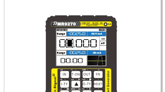
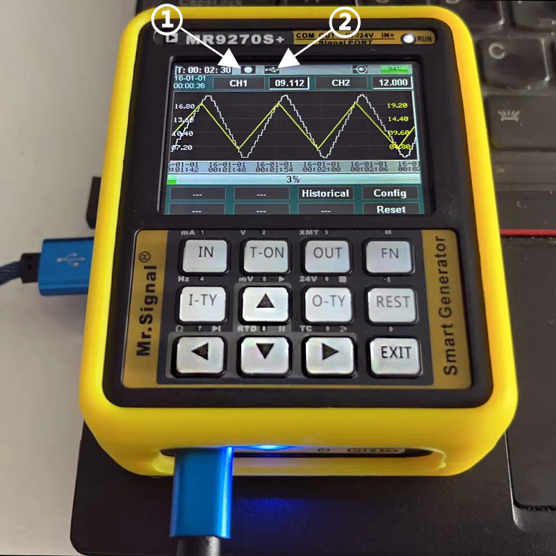
Instrument introduction1.MR9270 adopts high-speed ARM processor, with powerful performance and man-machine dialogue interface, which is easy to use. The following figure is the structure diagram of the。 |
|
|---|---|
1 |
COM(Common signal port) |
2 |
OUTPUT(The signal output port can output Ma, V, Hz, MV, Ω and 24V signals) |
3 |
In – (signal input port, which can output one channel of 24V separately after activating 24V function) |
4 |
In + (signal output, capable of outputting Ma, V, Hz, MV, Ω, 24V signals) |
5 |
Signal output module (MA, V, Hz, MV, Ω,) |
6 |
24V |
7 |
Signal input module (MA, V, Hz, MV, Ω,) |
8 |
2.4 “IBS HD LCD |
9 |
Signal generator operation panel |
10 |
Buzzer |
11 |
MR9270 kernel layer |
12 |
Power module (2500ma polymer lithium battery * 1) |
13 |
USB power interface (external power 5V / 1a) |
14 |
RS485 conversion interface |
-1-
(Click to return to the directory)
Introduction to practical functions |
|
|---|---|
Programming output |
The user can automatically raise and lower the MR9070 signal output, with two modes. The first method: set the start point, end point and cycle times to start working. The second: advanced mode, the signal changes are all set by parameters. |
Preset value |
9 groups of commonly used signal values can be preset for fast output. |
Signal conversion |
The input signal is converted into an output signal. For example:
The input frequency is converted into current signal, and the input range is converted from 0 ~ 1000Hz to 4 ~ 20mA |
Real time curve |
The change trend of input and output signals can be displayed by curve, and the acquisition time of curve can be set,It can also automatically display the curve in the range of maximum and minimum values at a certain time. |
Quantity display conversion |
The signal is displayed as signal value or engineering quantity, and the signal value is linearly corresponding to the engineering quantity, such as 4-20mA The signal of corresponds to 0 ~ 100, that is, 4mA corresponds to 0, 12mA corresponds to 50 and 20mA corresponds to 100. This range can be changed through parameters. |
Mod bus RTU remote control |
RS485 communication can be carried out with configuration software or PLC to realize on-line setting of instrument output signal and monitoring Input signal of the instrument. |
Mod bus RTU master station |
Conduct communication test, parameter setting, parameter copy, online monitoring and other operations on the slave equipment with RS485 MODBUS interface. |
Instrument engineering set |
As a function expansion together, such as simple paperless recorder, PID controller, etc., please pay attention to it in detail This manual does not describe the product website. |
USB firmware upgrade |
Upgrade new firmware and expand new features. |
USB to Rs485 |
The instrument can be used as USB to RS485 virtual serial port, and the operating system below win10 needs to install driver |
-2-
(Click to return to the directory)
Mr9270 series signal parameter table |
|||||
|---|---|---|---|---|---|
Output signal parameters |
|||||
Signal |
Range |
Accuracy |
resolving power |
Internal resistance |
|
Current (mA) |
0~23mA |
0.03% |
0.001mA |
100Ω |
|
Voltage (V) |
0~23V |
0.03% |
0.001V |
500K |
|
Passive signal (XMT) |
0~24mA |
0.03% |
0.001mA |
100Ω |
|
24V circuit detection |
0~24mA |
0.03% |
0.01mA |
100Ω |
|
Frequency (Hz) |
0~9999Hz |
0.03% |
5位 |
1MK |
|
Millivolt (mV) |
-10~110mV |
0.05% |
0.01mV |
2K |
|
Thermocouple (TC-S) |
0~1760℃ |
0.10% |
1℃ |
2K |
|
Thermocouple (TC-B) |
0~1810℃ |
0.20% |
1℃ |
2K |
|
Thermocouple (TC-E) |
0~990℃ |
0.10% |
1℃ |
2K |
|
Thermocouple (TC-K) |
0~1320℃ |
0.10% |
1℃ |
2K |
|
Thermocouple (TC-R) |
0~1760℃ |
0.20% |
1℃ |
2K |
|
Thermocouple TC-J) |
0~1190℃ |
0.10% |
1℃ |
2K |
|
Thermocouple (TC-T) |
0~390℃ |
0.20% |
1℃ |
2K |
|
Thermocouple (TC-N) |
0~1290℃ |
0.20% |
1℃ |
2K |
|
Pt100 |
-200~650℃ |
0.30% |
1℃ |
— |
|
Cu50 |
-20~150℃ |
0.30% |
1℃ |
— |
|
Resistance output |
0~390Ω |
0.10% |
0.01Ω |
— |
|
Input signal parameters |
|||||
Signal |
Range |
resolving power |
resolving power |
Internal resistance |
|
Current (mA) |
-24~24mA |
0.03% |
0.001mA |
100Ω |
|
Voltage (V) |
-30~30V |
0.03% |
0.001V |
3M |
|
Frequency (Hz) |
0~9999Hz |
0.03% |
5位 |
100K |
|
Millivolt (mV) |
-110~110mV |
0.03% |
0.01mV |
20M |
|
Thermocouple(TC-S) |
0~1760℃ |
0.10% |
1℃ |
20M |
|
Thermocouple(TC-B) |
0~1810℃ |
0.20% |
1℃ |
20M |
|
Thermocouple(TC-E) |
0~990℃ |
0.10% |
1℃ |
20M |
|
Thermocouple(TC-K) |
0~1320℃ |
0.10% |
1℃ |
20M |
|
Thermocouple(TC-R) |
0~1760℃ |
0.10% |
1℃ |
20M |
|
Thermocouple(TC-J) |
0~1190℃ |
0.10% |
1℃ |
20M |
|
Thermocouple(TC-T) |
0~390℃ |
0.10% |
1℃ |
20M |
|
Thermocouple(TC-N) |
0~1290℃ |
0.10% |
1℃ |
20M |
|
Pt100 |
-200~650℃ |
0.30% |
1℃ |
10K |
|
Cu50 |
-20~150℃ |
0.50% |
1℃ |
10K |
|
Resistance input |
0~400Ω |
0.10% |
1℃ |
10K |
|
-3-
(Click to return to the directory)
Basic operation |
|
|---|---|
1. |
Signal output (positive) |
2. |
Signal input (negative)/24V |
3. |
Signal output (negative)/com |
4. |
Signal input (positive) |
5. |
Type-C charging interface |
6. |
RS485 communication interface |
7. |
charge indicator |
8. |
Power switch (long press for 2 seconds to turn on and off) |

-4-
(Click to return to the directory)
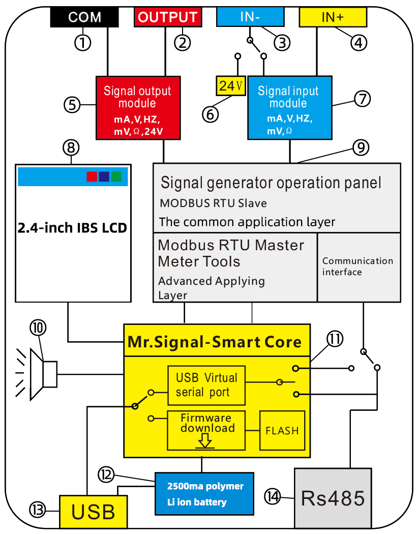
Introduction to keyboard functions |
|---|
 |
Comparison table of operation keys |
|
|---|---|
“  ” This is the input key ” This is the input key |
① : press the “IN” key once to call up the input signal interface. The displayed signal type corresponds to the corresponding key on the keyboard. For the signal type you need, just press the corresponding key to switch to the signal type you need. ② : In the instrument, the “IN” key is also used for confirmation, entry and switching. For example, when you open an interface in the instrument, the “IN” key is confirmation, entry and switching at this time. ③ : Long press the “IN” key to pop up the signal input setting interface, exit the signal input setting interface and press the “EXIT” key ④ : The “IN” key corresponds to the current signal (MA) |
“  ” key ” key |
① : the “T-ON” button is the switch for signal output ② : after the signal selection interface pops up through the “IN” key or “OUT” key, “T-ON” key corresponds to the “voltage” signal. |
“  ” This is the output key ” This is the output key |
① : press the “OUT” key once to call up the output signal interface. The signal type presented corresponds to the corresponding key on the keyboard. For the signal type you need, just press the corresponding key to switch to the signal type you need. ② : Long press the “OUT” key to pop up the output setting interface ③ : Press the “OUT” key to pop up the output signal selection interface, and the “OUT” key corresponds to the “passive current” signal. |
“  ” key ” key |
① : the “FN” key is a function menu key. ② : long press the “FN” key to pop up the preset function ③ : press the “IN” key to pop up the input signal selection interface, and press the “FN” key to quickly activate the “signal conversion” mode. To exit this mode, simply press the “EXIT” key. Shortcut function: you can enter the menu for replacement. ④ : press the “OUT” key to pop up the output signal selection interface, and then press the “FN” key to quickly activate the “signal programming output mode”. To exit this mode, simply press the exit key. |
“  ” key ” key |
① : after the signal selection interface pops up through the “IN” key or “OUT” key, press the “I-TY” key to correspond to the “Hz” signal. ② : after the input signal is switched to the “frequency” signal, press the “I-TY” button to switch the three modes of frequency. Pulse / RPM speed / PWM / count. ③ : When the input signal is switched to the “millivolt” signal, press the “in mode” key to pop up the thermocouple type selection interface. The thermocouple type in the interface corresponds to the corresponding key on the keyboard. ④ : after the input signal is switched to the “resistance” signal, long press the “I-TY” key to call out the resistance input type, and the signal type in the interface corresponds to the corresponding key on the keyboard. Press the “I-TY” button once to quickly switch the signal input type. ⑤ : when the input signal is switched to the “PT100” signal, long press the “I-TY” key to call out the resistance input type, and the signal type in the interface corresponds to the corresponding key of the keyboard. Press the “I-TY” button once to quickly switch the signal input type. ⑥ : after the input signal is switched to the “mA” signal, press the “I-TY” button to switch the display of “engineering quantity” or “current value”. ⑦ : after the input signal is switched to the “voltage” signal, press the “I-TY” button to switch the display of “engineering quantity” or “voltage value”. |
“  ” key ” key |
① : press the “OUT” key to pop up the output signal selection interface, and the “O-TY” key corresponds to “24V circuit detection”. ② : when the output signal is switched to the current signal, press the “O-TY” key to switch between “engineering quantity” and “current signal value”. ③ : after the output signal is switched to the voltage signal, press the “O-TY” key to switch between “engineering quantity” and “voltage signal value”. ④ : after the output signal is switched to the “Hz” signal, long press the “O-TY” key to switch three frequency modes. Pulse / PWM / RPH / quantitative. (specific pulse operation will be described later) ⑤ : When the output signal is switched to the “millivolt” signal, press the “out mode” key to pop up the thermocouple mode selection interface. The thermocouple type in the interface corresponds to the corresponding key on the keyboard. ⑥ : After the output signal is switched to the “resistance” signal, long press the “out mode” key to call out the resistance input type. The signal type in the interface corresponds to the corresponding key on the keyboard. Press the “out mode” key once to quickly switch the signal input type. ⑦ : When the output signal is switched to the ‘PT100’ signal, long press the ‘out mode’ key to call up the resistance input type. The signal type in the interface corresponds to the corresponding key on the keyboard. Press the “out mode” key once to quickly switch the signal input type.
|
“  ” This is the reset key ” This is the reset key |
① : press “REST” key to reset the value. ② : press the “IN” key to pop up the signal input selection interface, and press the “REST” key to correspond to “REC”, This is a paperless recorder. After starting, you need to find the recorder from the tools in the menu and press the “IN” key to enter the interface ③ : press the “OUT” key to pop up the signal output selection interface, and press the “REST” key to correspond to “per”, which is the mode of “9 groups of signal preset” (before using this mode, you must enter the function menu to preset the signal, and the specific operation will be described later) |
“  ” button ” button |
① : the “EXIT” key has three functions: exit, return and cancel. ② : long press the “EXIT” key to switch the working interface. There are five different working interfaces ③ : press “EXIT” in the working interface to pop up the value input interface. The numbers in the interface correspond to the keys on the keyboard. Press the “FN” key to exit and confirm |
“  ” This is the direction key ” This is the direction key |
① : after the signal selection interface pops up through the “IN” key or “OUT” key, press the “←” key, the corresponding “ohm” is the resistance signal. |
“  ” This is the direction key ” This is the direction key |
① : after the signal selection interface pops up through the “IN” key or “OUT” key, press the “”↑”” key, and the corresponding “mV” is a millivolt signal. |
“  ” This is the direction key ” This is the direction key |
① : after the signal selection interface pops up through the “IN” key or “OUT” key, press the “↓” key, and the corresponding “RTD” is PT100. |
“  ” This is the direction key ” This is the direction key |
① : after the signal selection interface pops up through the “IN” key or “OUT” key, press the “→” key, and the corresponding “TC” is the thermocouple signal. |
-5-
(Click to return to the directory)
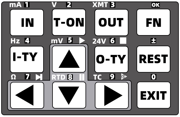
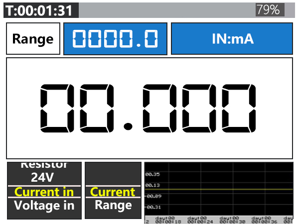
Description of work interface |
|---|
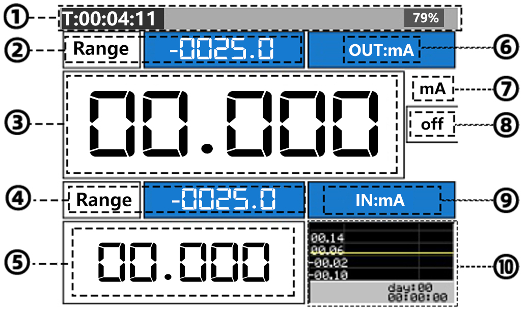 |
Working interface description cross reference table |
|
|---|---|
1. |
Status bar: used to display time, power supply, connection, record, etc. |
2. |
Output signal name and status box: used to display the engineering quantity of the current signal, the current signal name and other information. |
3. |
Output signal value box: press the “ “,”“, ““, “” keys to set the value of the signal, or quickly change the value through the preset signal function, or press the “EXIT” key to pop up the value input table, and use the value table to quickly input the signal value. |
4. |
Input signal name and status box: used to display the engineering quantity of the current signal, the current signal name and other information. |
5. |
Input signal value box: displays the signal value input externally. |
6. |
Name of the type of output signal |
7. |
Name and unit of output signal type |
8. |
Display of switch |
9. |
Name of the type of input signal |
10. |
Real time curve, you can switch to the full screen real-time curve display mode by long pressing the “EXIT” key three times. |
-6-
(Click to return to the directory)
Output signal type selection(press the “OUT” key once to pop up the signal output interface) |
|---|
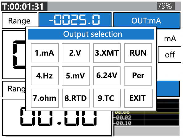 |
The output signal selection interface pops up by pressing the “OUT” key. The type of signal presented above corresponds to the corresponding key on the keyboard (see the figure below) |
|
Input signal type selection(Press the “IN” key once to pop up the signal input interface) |
 |
Press the “IN” key to pop up the input signal selection interface. The signal type shown above corresponds to the corresponding key on the keyboard (see the figure of the keyboard) |
-7-
(Click to return to the directory)
Current output setting(Switch the output signal to the current signal “mA”, press and hold the “OUT” key for 1 to 2 seconds to pop up the current output setting interface) |
|
|---|---|
|
(1-2) |
①  |
Return and exit the interface, or press the “EXIT” key directly to exit |
②  |
Mode switching. Move the cursor to “Mode” and press “IN” to switch between “actual output” and “range output”. |
③  |
Loop Vol. no load voltage, move the cursor to “loop Vol” and press “IN” to switch the voltage. The default value is “16.5v”. The purpose is to save power. It can be switched to “24V” as needed |
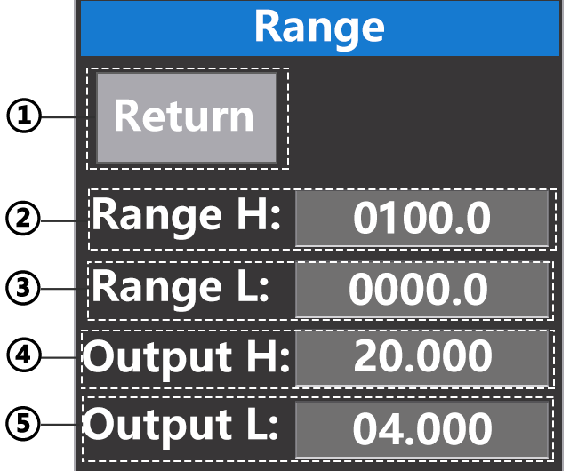
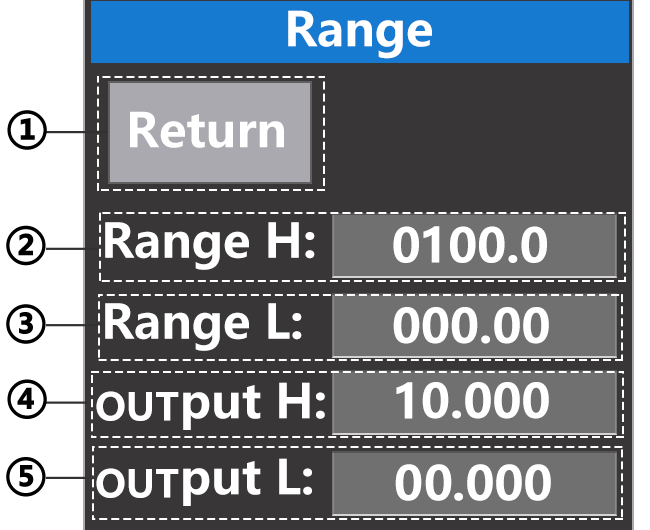
④  |
Set the range, move the cursor to “range”, press “IN” to enter, and the range setting interface pops up (refer to Figure 1-2 above) ①:Return and exit the interface, or press the “EXIT” key directly to exit ② : upper limit of the scope of quantities ③ : lower limit of the scope of quantities ④ : output upper limit ⑤ : lower output limit |
⑤  |
Output range, move the cursor to “out range”, press the “IN” key to enter the selection mode, move the cursor to the required value range, and press the “IN” key to confirm the selection |
Current output wiring diagram |
|
 |
|

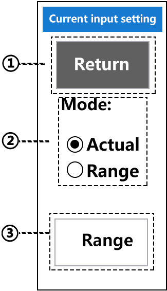
Current input setting(Switch the input signal of the instrument to the current signal “mA”, press and hold the “IN” key for 1-2 seconds to pop up the input current signal setting interface) |
|
 (1-1) |
①:Return and exit the interface, or press the “EXIT” key directly to exit
②:Mode switching. Move the cursor to “Mode” and press “IN” to switch between “actual output” and “range output”. ③:Set the range, move the cursor to “Range”, press “IN” to enter, and the range setting interface pops up (refer to Figure 1-2 below) |
(1-2) |
①:Return and exit the interface, or press the “EXIT” key directly to exit ② : upper limit of the scope of quantities ③ : lower limit of the scope of quantities ④ : output upper limit ⑤ : lower output limit |
Current input wiring diagram |
|
 |
|
-8-
(Click to return to the directory)
Voltage input setting(switch the instrument input signal to the voltage signal, press and hold the “IN” key for 1-2 seconds to pop up the input voltage signal setting interface) |
|
(1-1) |
①:This is to return, or you can directly press the “EXIT” key to exit ②:Mode switching. Move the cursor to “Mode” and press “IN” to switch between “actual output” and “range output”. ③:Set the range, move the cursor to “Range”, press “IN” to enter, and the range setting interface pops up (Refer to figure 1-2 below) |
|---|---|
(1-2) |
① : return to and exit the interface, or press the “EXIT” key directly to exit ② : upper limit of the scope of quantities ③ : lower limit of the scope of quantities ④ : enter upper limit ⑤ : enter lower limit |
Voltage input wiring diagram |
|
(-30V~30V) |
|
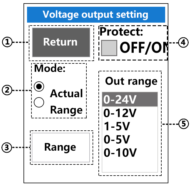
Voltage output setting(switch the instrument output signal to the voltage signal, press and hold the “OUT” key for 1-2 seconds to pop up the output voltage signal setting interface) |
|
 (1-3) |
①:This is to return, or you can directly press the “EXIT” key to exit ②:Mode switching. Move the cursor to “Mode” and press “IN” to switch between “actual output” and “range output”. ③:Set the range, move the cursor to “Range”, press “IN” to enter, and the range setting interface pops up (Refer to figure 1-4 below) ④:This is a protection function. Move the cursor to “protect” and press the “IN” key to turn on or turn off the protection. The function is to turn off the output automatically if the output voltage is short circuited for 2 seconds ⑤:Output range, move the cursor to “Out range”, press the “IN” key to enter the selection mode, move the cursor to the required value range, and press the “IN” key to confirm the selection |
 (1-4) |
① : return to and exit the interface, or press the “EXIT” key directly to exit ② : upper limit of the scope of quantities ③ : lower limit of the scope of quantities ④ : output upper limit ⑤ : lower output limit |
Voltage output wiring diagram |
|
|
|


-9-
(Click to return to the directory)
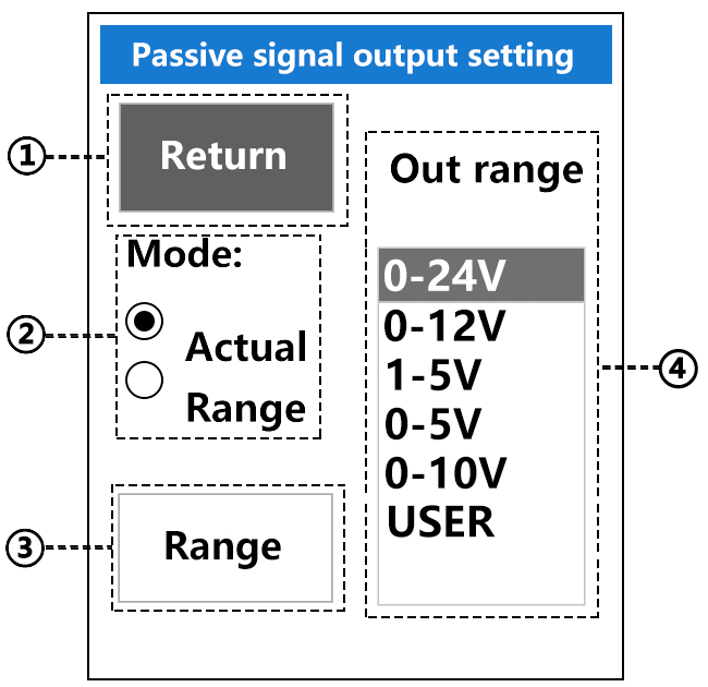
Passive signal output setting(switch the instrument output signal to the passive signal, press and hold the “OUT” key for 1-2 seconds to pop up the passive signal setting interface) |
|
|---|---|
(1-1) |
①:This is to return, or you can directly press the “EXIT” key to exit ②:Mode switching. Move the cursor to “Mode” and press “IN” to switch between “actual output” and “range output”. ③:Set the range, move the cursor to “Range”, press “IN” to enter, and the range setting interface pops up (Refer to figure 1-2 below) ④:Output range, move the cursor to “out range”, press the “IN” key to enter the selection mode, move the cursor to the required value range, and press the “IN” key to confirm the selection |
(1-2) |
① : return to and exit the interface, or press the “EXIT” key directly to exit ② : upper limit of the scope of quantities ③ : lower limit of the scope of quantities ④ : output upper limit ⑤ : lower output limit |
Passive signal output wiring diagram |
|
 (COM)/(OUT)/(IN-24v)/(IN+<30V) (Output passive signal to digital display instrument / PLC / isolation safety barrier and other equipment) |
|
-10-
(Click to return to the directory)
Four modes of pulse signal(Note1:Call up the interface below to view page 7 above) (Note 2: after the output signal is switched to “Hz”, long press the “O-TY” key to switch between the four modes. Pressing the “O-TY” key once is the switching unit) (Note3: after the input signal is switched to “Hz”, press the “I-TY” key once to switch between the four modes ) |
|
|---|---|
Frequency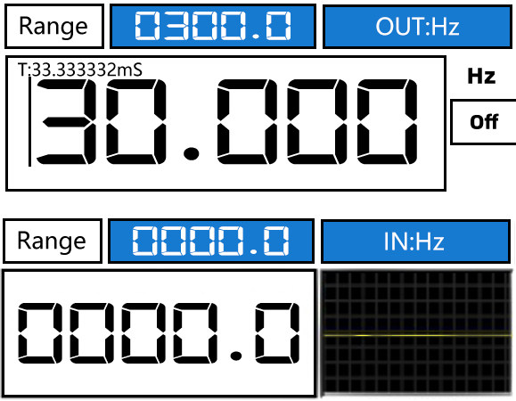
|
PWM duty cycle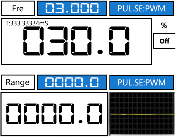
|
Rotational speed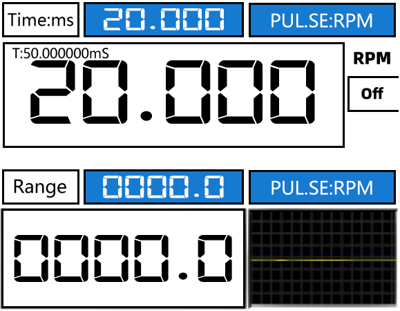
|
pulse quantitative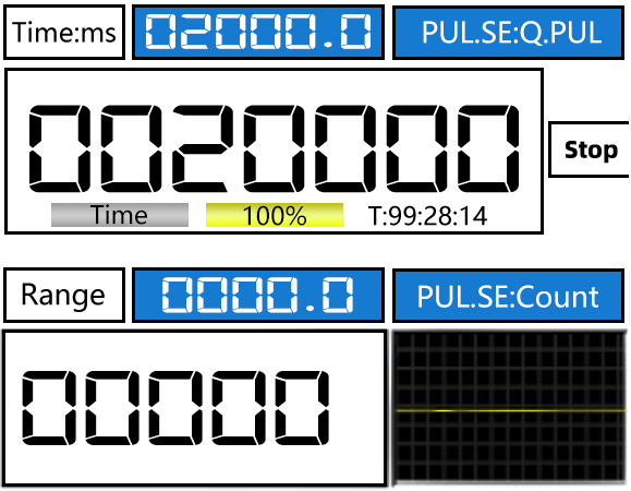
|
-11-
(Click to return to the directory)
Description of four pulse signal modes |
|
|---|---|
Frequency |
The frequency belongs to the most commonly used signal in pulse signals and has four ranges. When outputting Hz signals, you can quickly switch the output range by pressing the “O-TY” key. |
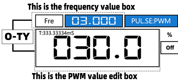
PWM mode |
PWM is the abbreviation of pulse width modulation, which is the time proportion of level on and hold in a pulse cycle. As can be seen from Figure 1-1 below, PWM requires two parameters. Therefore, it is necessary to set the frequency value, that is, the cycle value, before outputting PWM. The setting method is to press the “O-TY” key once to switch to the frequency value editing (see Figure 1-2 below). After setting the frequency value, press the “O-TY” key once to switch to the PWM editing.
 (1-1)
(1-2) Press the “O-TY” key to switch the value editing between PWM and Fre |
Speed mode |
The best way to calculate the speed of the motor or gear is to use the pulse mode. The motor is usually in minutes. If one pulse is generated in one revolution of the motor, one minute is 3000 revolutions, then one second is 50 pulses.
①:Frequency and frequency value box ② : set the number of revolutions of the motor shaft, and the upper left corner is the time of one cycle ③ : pulse M
|
Count |
The main purpose of pulse quantitative control is to simulate the flow quantitative control sensor, for example: One liter of water flow from the turbine sensor generates 100 pulses through the sensor, so 10 liters of water is 1000 pulses. When writing the PLC quantitative program, the generator can be used for accurate simulation.
( Note 1: before setting the pulse quantity and pulse sending time, you must first press the “T-ON” key to switch the working state of the instrument to “stop” (see figure ⑦ above), and then press the “O-TY” key to switch the cursor to the pulse sending time. After setting the time (see figure ① above), press the “O-TY” key to switch the cursor to the pulse number setting, and then set the pulse number (see figure ③ above). After the time and pulse are set, Press the “T-ON” key to switch the working state to “pause”, and then press the “↑” key to start sending pulses Note2: Press “↑” to send pulses, press “↓” to pause sending pulses, and press “REST” to set the set value to zero. Note3: after starting to send pulses, press “ ①:Time to send 1 pulse, minimum 0.1 Ms. Press the “O-TY” key in the case of pause to switch to the time setting of sending 1 pulse ②:Time unit for sending 1 pulse ③:Quantitative number of pulses, press “ ④:Send 1 pulse time progress bar ⑤:Progress bar for number of pulses remaining ⑥:Progress of remaining sending time ⑦:working condition
|
 =
=  (per second) × Number of pulses per revolution
 (per minute) =
  (per hour) =
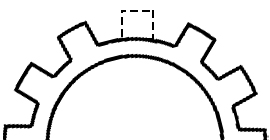
 This function is used to simulate the engine speed. For example, the engine gear has 60 teeth, but now assuming that the engine gear has one tooth less and only 59 teeth, the speed can be measured through the empty space without teeth
 =Stop
=Stop  =Pause)
-12-
(Click to return to the directory)
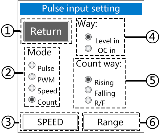
Frequency input signal setting(Switch the instrument input signal to frequency signal, press and hold the “IN” key for 1-2 seconds to pop up the frequency signal input setting interface) (Note: after entering the setting interface, use the “ |
|
|---|---|
 (1-1) |
①:return to and exit the interface, or press the “EXIT” key directly to exit. ②:Move the cursor to “Mode”, press “IN” key to switch between “Pulse” / “PWM” / “Speed” / “Count” ③:Set the speed, move the cursor to “SPEED”, and press the “IN” key to enter(see Figure 1-2 below for details) ④:Pulse signal input mode:”Level in”(Pulse input with electricity)/”OC in”(Switch input) ⑤:Counting method:”Rising”(Record once when the electric pulse drops from 0V to greater than or equal to 0.7V)”Falling”/(Record once when the electric pulse drops from greater than or equal to 0.7V to 0V)/(“R/F”:As long as there is a rise and fall process, it will be recorded once)To clear the count, press the “REST” key ⑥:Range setting(see Figure 1-3 below for details) |
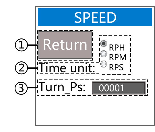 (1-2) |
① : return to and exit the interface, or press the “EXIT” key directly to exit. ②:Move the cursor to “Time unit:”, press “IN” to switch between “RPH” / “RPM” / “RPS” ③:Move the cursor to “Turn Ps:” and press the “IN” key to enter the editing state |
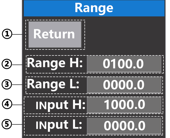 (1-3) |
① : return to and exit the interface, or press the “EXIT” key directly to exit ② : upper limit of the scope of quantities ③ : lower limit of the scope of quantities ④ : enter upper limit ⑤ : enter lower limit |
Wiring diagram |
|
 Sensor wiring for OC gate frequency output(Input range 0-9999Hz) |
|
 Sensor wiring for PNP frequency output(Input range 0-9999Hz) |
|
-13-
(Click to return to the directory)
Frequency output signal setting(switch the instrument output signal to frequency signal, press and hold the “OUT” key for 1-2 seconds to pop up the frequency signal output setting interface) (Note: after entering the setting interface, use the “↑” key or “↓” key to move the cursor) |
|
|---|---|
 1-1 |
① : return to and exit the interface, or press the “EXIT” key directly to exit. ② : press the “IN” key to enter the selection mode, confirm the selection, and then press the “IN” key once ③ : press the “IN” key to enter the selection mode, confirm the selection, and then press the “IN” key once ④ : pulse signal output mode: level output (power on pulse output) / OC output (switch output) ⑤:Set the speed, move the cursor to “SPEED”, and press the “IN” key to enter(see Figure 1-2 below for details) ⑥:Range setting(see Figure 1-3 below for details) ⑦:Height of level output, up to 24V Move the cursor to “Peak:” and press the “IN” key to enter the editing mode. After confirming the editing, press the “IN” key once
|
 1-2 |
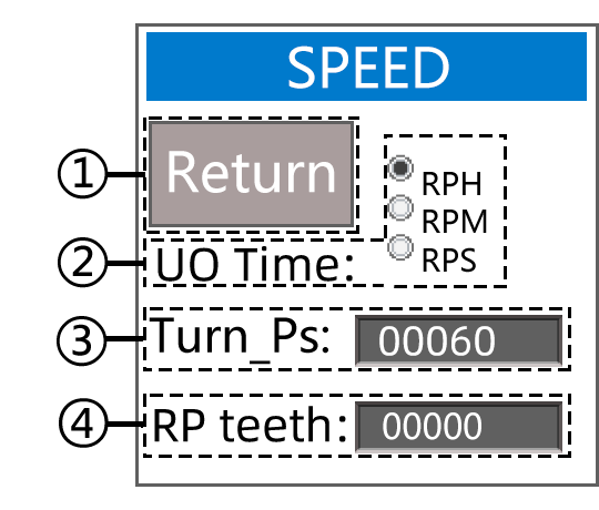
(Long press the “O-TY” key to quickly switch the pulse output mode, and press the “O-TY” key once to change the unit) ① : return to and exit the interface, or press the “EXIT” key directly to exit. ②:Move the cursor to “Time unit:”, press “IN” to switch between “RPH” / “RPM” / “RPS” ③:Move the cursor to “Turn Ps:” and press the “IN” key to enter the editing state ④:Missing tooth simulation. Simulate that the engine gear lacks a tooth, and measure the speed through the missing tooth |
 1-3 |
① : return to and exit the interface, or press the “EXIT” key directly to exit ② : upper limit of the scope of quantities ③ : lower limit of the scope of quantities ④ : enter upper limit ⑤ : enter lower limit |
Wiring diagram |
|
Level output |
|
|
Open circuit output |
|


-14-
(Click to return to the directory)
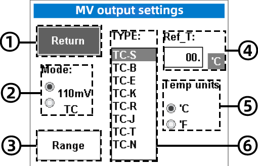
Millivolt output setting(switch the instrument output signal to millivolt signal, press and hold the “OUT” key for 1-2 seconds to pop up the millivolt signal output setting interface) |
|
|---|---|
 (1-1) (1-1) |
① : return to and exit the interface, or press the “EXIT” key directly to exit ② : press the “IN” key to enter the selection mode, confirm the selection, and then press the “IN” key once ③:Set the range, move the cursor to “Range”, press “IN” to enter, and the range setting interface pops up (Refer to figure 1-2 below) ④: press the “IN” key to enter the cold end compensation editing mode, and press the “IN” key once after editing the value to confirm (this is the cold end compensation setting) ⑤: “Temp unit:”, press the “IN” key to switch the temperature unit (this is the temperature unit) ⑥: press the “IN” key to enter the selection mode, confirm the selection, and then press the “IN” key once (this is the type of thermocouple) |
 (1-2) (1-2) |
① : return to and exit the interface, or press the “EXIT” key directly to exit ② : upper limit of the scope of quantities ③ : lower limit of the scope of quantities ④ : enter upper limit ⑤ : enter lower limit |
Wiring diagram |
|
Instrument or PLC |
|
Millivolt input settings(switch the instrument input signal to millivolt signal, press and hold the “IN” key for 1-2 seconds to pop up the millivolt signal input setting interface) |
|
 (1-1) (1-1)
|
① : return to and exit the interface, or press the “EXIT” key directly to exit ② : press the “IN” key to enter the selection mode, confirm the selection, and then press the “IN” key once ③:Set the range, move the cursor to “Range”, press “IN” to enter, and the range setting interface pops up (Refer to figure 1-2 below) ④: press the “IN” key to enter the cold end compensation editing mode, and press the “IN” key once after editing the value to confirm (this is the cold end compensation setting) ⑤: “Temp unit:”, and press the “IN” key to switch the temperature unit (this is the temperature unit) ⑥:press the “IN” key to enter the selection mode, confirm the selection, and then press the “IN” key once (this is the type of thermocouple) |
 (1-2) (1-2)
|
① : return to and exit the interface, or press the “EXIT” key directly to exit ② : upper limit of the scope of quantities ③ : lower limit of the scope of quantities ④ : enter upper limit ⑤ : enter lower limit |
Wiring diagram |
|
|
Thermocouple sensor |
|

-15-
(Click to return to the directory)
Resistance output setting(switch the instrument output signal to resistance signal, press and hold the “OUT” key for 1-2 seconds to pop up the resistance signal output setting interface) |
|
|---|---|
 |
① : return to and exit the interface, or press the “EXIT” key directly to exit ② : “Temp unit:”, and then press the “IN” key to switch the temperature unit (this is the temperature unit) ③: press the “IN” key to enter the resistance value editing mode (this is the resistance value offset, which is used to correct the output resistance value) ④:press the “IN” key to enter the selection mode, confirm the selection, and then press the “IN” key once(this is the type selection of thermal resistance) |
Wiring diagram |
|
Instrument or PLC |
|
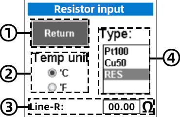
Resistance input setting(switch the instrument input signal to resistance signal, press and hold the “IN” key for 1-2 seconds to pop up the resistance signal input setting interface) |
|
|
① : return to and exit the interface, or press the “EXIT” key directly to exit ② : “Temp unit:”, and then press the “IN” key to switch the temperature unit (this is the temperature unit) ③: press the “IN” key to enter the resistance value editing mode (this is the resistance value offset, which is used to correct the output resistance value) ④: press the “IN” key to enter the selection mode, confirm the selection, and then press the “IN” key once(this is the type selection of thermal resistance) |
Wiring diagram |
|
 |
|
-16-
(Click to return to the directory)
24V circuit detection(switch the instrument output signal to “24V”, press and hold the “OUT” key for 1-2 seconds to pop up the 24V output setting interface) |
|
|---|---|
(Press “O-TY” key to switch mode) |
|
 1-1 1-1 |
①:This is to return, or you can directly press the “EXIT” key to exit ②:Mode switching. Move the cursor to “Mode” and press “IN” to switch between “actual output” and “range output”. ③:Set the range, move the cursor to “Range”, press “IN” to enter, and the range setting interface pops up (Refer to figure 1-2 below) |
 1-2 1-2 |
① : return to and exit the interface, or press the “EXIT” key directly to exit ② : upper limit of the scope of quantities ③ : lower limit of the scope of quantities ④ : enter upper limit ⑤ : enter lower limit |
Wiring diagram |
|
| Transmitter
 |
|
Independent 24V(Press the “FN” key to enter the function menu. After the cursor moves to “USE 24V”, press the “IN” key to enter) |
|
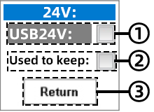 |
① : move the cursor to “USE 24V:”, press the “IN” key to tick, and 24V will be activated ② : “Used to keep:”when this option is checked, the 24V activation status will be automatically turned on each time the machine is powered on ③ : return to and exit the interface, or press the “EXIT” key directly to exit |
 |
Input (-) can be switched to independent 24V function, which is 24V of one channel of independent output 24V interface can be used with input (+) to test the transmitter. It is mainly used to test pneumatic valve or two-wire transmitter |

Wiring diagram |
||
| Note: test the wiring method of two-wire transmitter independently. The “independent 24V” terminal is connected to the positive pole and the input (+) is connected to the negative pole. | ||
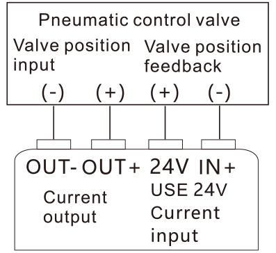 Pneumatic control valve test |
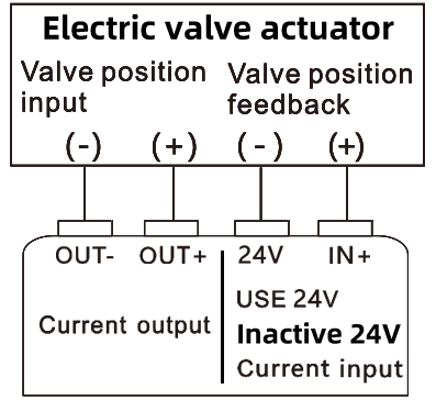 Electric valve actuator |
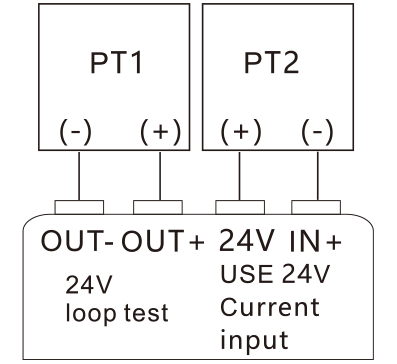 Test two two-wire transmitters at the same time |
-17-
(Click to return to the directory)
Function menu |
|
|---|---|
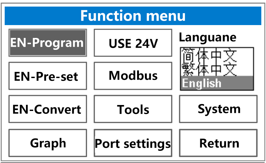
(1-1) |
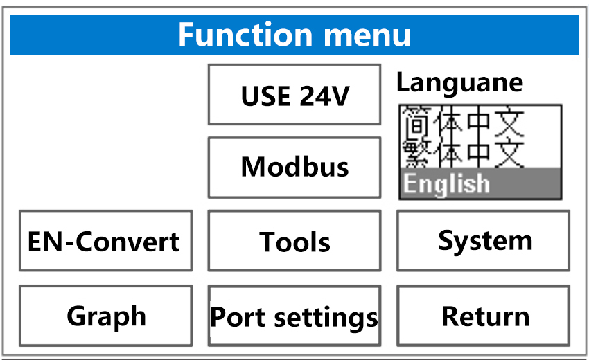
(1-2) |
| Note: when the output signal is switched to “24V loop”, there are also some changes in the function menu interface, as shown in Figure 1-2 | |
 |
This is the programming output. Move the cursor to “EN- Program” and press the “IN” key to edit the output signal |
 |
Enable the preset signal function, move the cursor to “EN-Pre-set” and press “IN” to enter |
 |
Enable signal conversion. Move the cursor to “EN Convert” and press “IN” to enable |
 |
Real time curve. Move the cursor to “Graph” and press “IN” to enable |
 |
Activate 24V, move the cursor to “USE 24V” and press “IN” to enter |
 |
Modbus master station, move the cursor to “Modbus” and press “IN” to enter |
 |
Tool, move the cursor to “Tools” and press “IN” to enter, you can see “recorder” and “PID panel” |
 |
Communication setting, which is the communication setting of Modbus master station. Move the cursor to “port settings” and press “IN” to enter |
 |
Return, this is to return or exit the function menu |
 |
For system settings, move the cursor to “System” and press “IN” to enter |
 |
For language switching, move the cursor to “Language” and press “IN” to enter the switching mode. After moving the cursor to the language you need, press “IN” to confirm the selection. |
-18-
(Click to return to the directory)
System settings |
|
|---|---|
 |
|
1. |
Backlight, the brightness of backlight can be reduced by pressing the “IN” key and enhanced by pressing the “T-ON” key |
2. |
Automatic shutdown, move the cursor to “AUTO OFF”, press “IN” to enter the option, select the required items and press “IN” to confirm. |
3. |
Save Value, press “FN” to enter the function menu, move the cursor to “System”, press “IN” to enter, move the cursor to “ save value:”, press “IN” to confirm the check, and then press “EXIT” to return to the working interface, Set the output signal to 20mA output (the output signal here is only an example), then turn off and start again, and the output signal is 20mA. Normally, if “save value” is not selected, the turn off and start again signal will be set to zero. Therefore, this function can be checked or unchecked according to the use requirements |
4. |
Press “T-ON” in the working interface to turn on the output signal switch, enter the system setting of the function menu, move the cursor to “save state:”, press “IN” to confirm and check, and the signal output state will be maintained after shutdown and restart. This function can be selected or not according to the use situation. |
5. |
Enter the system setting of the function menu, move the cursor to “screen:”, press the “IN” key to enter the selection mode, and press the “IN” key to confirm the work interface. |
6. |
USB & no, move the cursor to “USB & no”, press “IN” to confirm the selection, and then the instrument can be powered by external 5V / 1A power supply |
7. |
Enter the system setting of the function menu, move the cursor to “Theme”, press the “IN” key to enter the selection mode, and press the “IN” key to confirm the theme of the instrument. |
8. |
Enter the system setting of the function menu, move the cursor to “FN function”, press the “IN” key to enter the selection mode, press the “IN” key to confirm the long press function of the “FN” key: ① : the first is “programming output” ② : the second is “preset of signal output” ③ : the third is “signal conversion” ④ : the fourth is “recorder” ⑤ : the fifth is “MODBUS master” |
9. |
Buzzer, press “IN” key to turn it on or off |
10. |
For signal calibration, press the “IN” key to enter(see page 22 for details) |
11. |
Quickly collect the signal, move the cursor to “fast ADC:”, and press “IN” key to confirm the selection. This function can improve the measurement speed. Turn on as needed |
12. |
Press the “EXIT” key to return or exit |
-19-
(Click to return to the directory)
Digital interface |
|
|---|---|
 (1-1) |
(1-2) |
| The numeric keypad pops up by pressing the “EXIT” key. The numbers in the above figure (1-1) correspond to the keys in figure (1-2) | |
1/- |
“1 / -” corresponds to the “IN” key. Pressing the “IN” key once will enter “1” in the value box, and long pressing the “IN” key will enter “-” in the value box. |
2/+ |
“2 / +” corresponds to the “T-ON” key. Press the “T-ON” key once to enter “2” in the value box, and long press the “T-ON” key to enter “+” in the value box. |
3 |
“3” corresponds to the “OUT” key. Press the “OUT” key once and enter “3” in the value box |
O K |
The “OK” key is to confirm and exit |
4 |
“4” corresponds to the “I-TY” key. Press the “I-TY” key once and enter “4” in the value box |
5 |
“5” corresponds to the “↑” key. Press the “↑” key once and enter “5” in the value box |
6/< – |
“6 / < -” corresponds to the “O-TY” key. Press the “O-TY” key once to output the number “6”. Long press the “O-TY” key once to delete one digit. Press once to delete only one digit. |
./C |
“./C” corresponds to the “REST” key. Press the “REST” key once and enter “.” in the value box |
7 |
“7”; corresponds to the “←” key. Press the “←” key once and enter “7” in the value box |
8 |
“8” corresponds to the “↓” key. Press the “↓” key once and enter “8” in the value box |
9 |
“9” corresponds to the “→” key. Press the “→” key once and enter “9” in the value box |
0 |
“0” corresponds to the “EXIT” key. Press the “EXIT” key once and enter “0” in the value box |
-20-
(Click to return to the directory)
Introduction to working interface(The operation mode of all work interfaces is the same) |
|
 1.Display of output signal |
 2.Display of input signal |
|---|---|
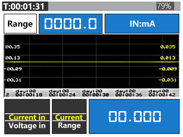 3.Enter the display of the real-time curve |
 4.Display of input-output real-time curve |
(The above working interfaces can be switched by long pressing “EXIT”) |
|
-21-
(Click to return to the directory)
Signal calibration(Note 1: this function can be used to calibrate its own signal only when the signal accuracy deviation of the signal generator is small) (Note 2: when using the calibration function, first long press the “EXIT” key to switch the working interface to the “working interface of input and output real-time curve”, that is, the last working interface. Then, Figure 1-2 below is an example of calibration operation, in which “20mA:” It is the maximum value. Before calibrating the current input signal, it is necessary to set the input current signal to 20mA. During calibration, “0ma:” in the figure is the minimum value. When calibrating the minimum value of the input current signal, it is also necessary to set the current signal to 0ma. The debugging methods of all signals are similar, and this example can be used for reference.) Example:Here, take the current signal input as an example (see Figure 1-1). After entering the calibration interface, move the cursor to “mA IN”, press the “IN” key to enter the current signal calibration interface (see Figure 1-2), move the cursor to “20mA:” press the “IN” key to enter the signal debugging mode, press the “↑” or “↓” key to debug the signal, and press “IN” after the current input signal is calibrated Press “EXIT” to exit the current calibration interface |
||||
|---|---|---|---|---|
(1-1) |
(1-2) |
|||
1. |
Current output |
①:Move the cursor to “20mA:” and press the “IN” key to enter the debugging mode, Then press the “↑” or “↓” key to debug the input signal. During debugging, see the digital box below for debugging. (Note: before debugging other signals, be sure to switch the working interface to the “input / output real-time curve working interface”, and then refer to “20mA:” in the current input calibration interface in Figure 1-2 above , adjust the input current signal to 20mA, and then calibrate it. All signal calibrations can use this example as a reference for calibration operation) ②:”0mA” is the minimum value. The operation method is as above. Adjust the minimum current signal to be debugged to “0mA”, and then conduct debugging and calibration (Note: all signals can be calibrated with reference to this example)
③:”- 20mA” is a negative value. The operation method is as above. Adjust the current signal to be debugged to “- 20mA”, and then conduct debugging and calibration (Note: all signals can be calibrated with reference to this example)
④:Return |
||
2. |
voltage output |
|||
3. |
passive output |
|||
4. |
millivolt output(Thermocouple type signals are also calibrated by commissioning millivolts) |
|||
5. |
resistance output(PT100 is calibrated by debugging the resistance signal) |
|||
6. |
Independent 24V |
|||
7. |
input current |
|||
8. |
voltage input |
|||
9. |
millivolt input(Thermocouple type signals are also calibrated by commissioning millivolts) |
|||
10. |
resistance input(PT100 is calibrated by debugging the resistance signal) |
|||
11. |
Return |
|||


-22-
(Click to return to the directory)
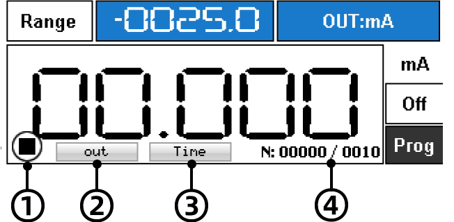
Programming output(press the “FN” key to enter the function menu, move the cursor to “EN-Program”, and press the “IN” key to enter. Or press the “OUT” key to call up the output signal interface, select “RUN” and press the corresponding “FN” key ) (press “EXIT” key to exit this function) |
|
|---|---|
 1-1 |
① : move the cursor to “Start” and press “IN” to start ② : press the “IN” key to switch the default cycle or custom mode(refer to Figure 1-1 for default cycle settings and figure 1-4 for custom settings) ③ : for the initial value, press the “IN” key to enter the editing mode. After editing, press the “IN” key to exit the editing mode ④ : end value, press the “IN” key to enter the editing mode. After editing, press the “IN” key to exit the editing mode ⑤:Time setting of increase / decrease cycle. Press the “IN” key to enter the editing mode. After editing, press the “IN” key to exit the editing mode ⑥ : advanced options, press “IN” to enter (see Figure 1-4 for details) |
(1-2)① : status icon ② : progress from start to end of signal ③ : scheduled progress ④ : number of remaining cycles |
|
| 1-3 |
“↑” key: program running “←” key: single step operation (only available when suspended) “↓” key: program pause “→” key: the program runs once “O-TY” key: program reset “EXIT”key: exit the program |
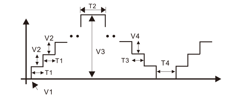
 1-4 1-4 |
① : return to the exit interface, or directly press the ‘in’ key to exit ② : Press’ in ‘key to cut cycle / customize(select custom, set the value in the advanced panel, and then restart the programming output to take effect.) ③ : press the “in” key to edit the increment value, and confirm to press the “in” key to exit ④ : press the “in” key to edit the increment value time, and confirm to press the “in” key to exit (for example, if the increment value is set to 1 and the increment time is set to 1, only one value will be added in 1 second) ⑤ : press the ‘in’ key to edit the terminal dwell time, and confirm to press the ‘in’ key to exit (for example, the terminal dwell time is set to 5 seconds, and then output 4-20. After reaching 20, the dwell time is 5 seconds) ⑥ : press the “in” key to edit the decrement value, and confirm to press the “in” key to exit (the same as the increment value setting) ⑦ : press the ‘in’ key to edit the decreasing value time, and confirm to press the ‘in’ key to exit (the same as the increment value time setting) ⑧ : press the ‘in’ key to edit the dwell time of a cycle (for example, the dwell time is set to 10 seconds, then output 4-20, increase from 4 to 20, decrease from 20 to 4, and stay for 10 seconds to continue running) |
(Note: the following dimensions correspond to figure 1-4 above) V1=Starting value V2=③ T1=④ T2=⑤ V3=End value V4=⑥ T3=⑦ T4=⑧ |
|
-23-
(Click to return to the directory)
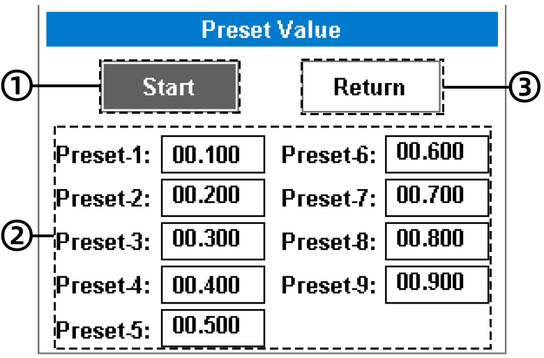
Preset value(Note 1: the preset cannot be used for the frequency signal. If the preset is used forcibly, the machine will crash, and the machine needs to be restarted to recover) (Note 2: before using the preset, switch the output signal to the signal type that needs to be preset, otherwise the preset will not work) (for example: to preset the current signal, it is necessary to switch the output signal to the current in advance, and to preset the voltage, it is necessary to switch the output signal to the voltage in advance, and other signal methods are the same) (Note3: the preset signal corresponds to the corresponding key. Please refer to Figure 1-2 below) (press “EXIT” key to exit this function) |
|
|---|---|
① : move the cursor to “Start” and press “IN” to start ②:9 groups of preset signals, move the cursor to the preset signal, press “IN” to enter the signal editing mode, complete the editing, and press “IN” to exit ③ : return to and exit the interface, or press the “EXIT” key directly to exit
|
 1-2 |
 1-1
1-1-24-
(Click to return to the directory)
Signal conversion(Press the “FN” key to enter the function menu, move the cursor to “EN-Convert”, and press the “IN” key to enter.) (press “EXIT” key to exit this function) (during on-site commissioning, if the commissioning equipment is inconsistent with the secondary instrument, this situation can be solved by signal conversion, for example, the frequency signal is converted from 0-100hz to 4-20mA) |
|
|---|---|
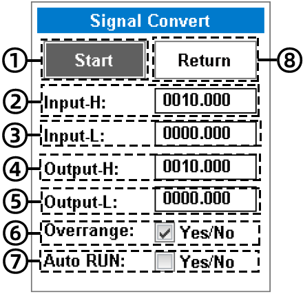 |
① : move the cursor to “Start” and press “IN” to start ② : enter the upper limit setting, move the cursor, press “IN” to enter the editing mode, complete the editing, and press “IN” to confirm and exit ③ : enter the lower limit setting, move the cursor, press “IN” to enter the editing mode, complete the editing, and press “”IN”” to confirm and exit ④ : output the upper limit setting, move the cursor, press “IN” to enter the editing mode, complete the editing, and press “IN” to confirm and exit ⑤ : output lower limit setting, move the cursor, press “IN” key to enter the editing mode, complete the editing, and press “”IN”” to confirm and exit ⑥ : allow the limit to be exceeded, move the cursor and press the “IN” key to tick (for example, 1-5V is converted to 4-20mA. If the limit is allowed to be exceeded, the output is adjusted to 0ma when the input is 0V. If the limit is not allowed to be exceeded, the output is 4mA when the input is 0V and the output is locked within the set range.) ⑦ : enable signal conversion when the machine is turned on, and the signal conversion function will be automatically turned on when the machine is turned on ⑧:return to and exit the interface, or press the “EXIT” key directly to exit |
-25-
(Click to return to the directory)
Real time curve settings(Press the “FN” key to enter the function menu, move the cursor to “Graph”, and press the “IN” key to enter.) (Long press the “EXIT” key to switch the working interface to the real-time curve interface) |
|
|---|---|
 |
(yellow is the output curve and white is the input curve) ① : auxiliary timer ② : signal value scale ③ : timescale |
 |
①:return to and exit the interface, or press the “EXIT” key directly to exit ② : output curve. Press the “IN” key to start, and the curve will also follow the display when the signal is output ③ : auto zoom. Press the “IN” key to start, automatically adjust the scale range of output signal, and automatically adjust the scale range of Y axis with the maximum and minimum value of curve. ④ : acquisition time. Press the “IN” key to start the refresh interval of the output curve ⑤ : auto zoom. Press the “IN” key to start, and the scale of the input signal will change automatically ⑥ : acquisition time. Press the “IN” key to start and input the refresh interval of the signal
|
| Tip: when modifying the acquisition time, the time scale will change automatically, and the time scale only follows the input signal acquisition | |
-26-
(Click to return to the directory)
Modbus master station(press the “FN” key to enter the function menu, move the cursor to “Modbus”, press the “IN” key to enter the configuration, as shown in Figure 1-1 below) (press the “FN” key to enter the function menu, move the cursor to “Port settings”, and press the “IN” key to enter the configuration, as shown in Figure 1-2 below) |
|
|---|---|
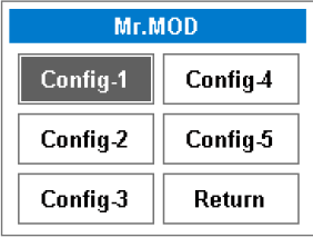 1-1 1-1The Modbus master station has five configurations for users to test different devices |
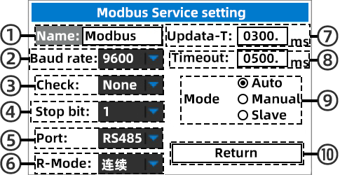
① : mode. The first uses 485 interface to use MODBUS slave, the second uses USB interface to use MODBUS slave, and the third uses USB interface to transfer to 485 interface to use MODBUS slave ② : baud rate. This is the communication rate. ③ : check bit ④ : stop bit ⑤ : set the device address. Set a communication address for the device ready for communication ⑥:return to and exit the interface, or press the “EXIT” key directly to exit |
 1-2
1-2Variable address and variable description (applicable to products after October 2021 |
|||
|---|---|---|---|
COM and OUT port output channels |
Address |
Function |
Data type |
40009 |
type of output |
16 bit unsigned |
|
40010 |
Signal mode |
16 bit unsigned |
|
40012 |
Output signal enable |
16 bit unsigned |
|
40017~40018 |
Output signal value setting |
32-bit signed integer |
|
“IN+” and “IN-” port measurement channels |
Address |
Function |
Data type |
40041 |
type of output |
16 bit unsigned |
|
40042 |
Signal mode |
16 bit unsigned |
|
40049~40050 |
Signal measurement value |
32-bit signed integer |
|
Signal type specification |
||
|---|---|---|
Signal function |
Code |
|
Signal type |
Signal mode |
|
Passive current output |
0 |
0 |
Active current output |
0 |
1 |
Current measurement |
0 |
128 |
Power distribution measurement (24V) |
0 |
129 |
Voltage |
||
Voltage output 0-24v |
1 |
0 |
Millivolt output 0-110mv |
1 |
2 |
Voltage measurement – 30-30v |
1 |
128 |
Millivolt measurement – 110mv-110mv |
1 |
130 |
Pulse |
||
Frequency output |
2 |
0 |
Speed output (RPS) |
2 |
2 |
Speed output (RPM) |
2 |
3 |
Speed output (RPH) |
2 |
4 |
PWM (0-100%) output |
2 |
5 |
Quantitative output |
2 |
6 |
Frequency measurement |
2 |
128 |
Speed measurement (RPS) |
2 |
130 |
Speed measurement (RPM) |
2 |
131 |
Speed measurement (RPH) |
2 |
132 |
PWM (0-100%) measurement |
2 |
133 |
Pulse count |
2 |
134 |
Resistance |
||
0-390 ohm output |
3 |
1 |
0-390 ohm measurement |
3 |
129 |
Thermal resistance |
||
PT100 |
4 |
0 |
Cu50 |
4 |
3 |
PT100 measurement |
4 |
128 |
Cu50 measurement |
4 |
131 |
Thermocouple |
||
K-type output |
5 |
0 |
R-type output |
5 |
1 |
S-type output |
5 |
2 |
E-type output |
5 |
3 |
J-type output |
5 |
4 |
T-type output |
5 |
5 |
N-type output |
5 |
6 |
B-type output |
5 |
7 |
WRE25-type output |
5 |
8 |
WRE26-type output |
5 |
9 |
K-type measurement |
5 |
128 |
R-type measurement |
5 |
129 |
S-type measurement |
5 |
130 |
E-type measurement |
5 |
131 |
J-type measurement |
5 |
132 |
T-type measurement |
5 |
133 |
N-type measurement |
5 |
134 |
B-type measurement |
5 |
135 |
WRE25-type measurement |
5 |
136 |
WRE26-type measurement |
5 |
137 |
Signal switching process: Take the output current signal as an example: 1: 40009 write signal type code is 0 2: 40010 write signal mode code is 1 3: 40012 write 1 enable output 4: Set input signal value (Note: after steps 1-3 are completed, only step 4 is required) |
||
Introduction to MODBUS master station(Enter the interface shown in the figure below through the configuration in Figure 1-1 above) |
|
|---|---|
 1. Master station label 2. Communication count 3. Error count 4. Baud rate information 5. Label of variable 6. Device address of variable 7. Address of variable 8. Data type 9. Number of variables 10. Value of variable 11. Online indication 12. Reading device(corresponding to “IN” key) 13. Pause / write data (corresponding to “T-ON” key.the option of writing data needs to change automatic writing to manual writing in the setting) 14. Add variables(corresponding to the “OUT” key. Press the “OUT” key to enter the interface of adding variables. See the following figure for details) 15. Setting(corresponding to the “FN” key. Press the “FN” key to enter the parameter setting interface of Modbus master station. See the following figure for details) |
|
(this is the interface for adding variables) (press the “OUT” key to enter the variable addition interface, and all editing operations are to press the “IN” key to edit or confirm editing) ① : OK. Move the cursor to “OK” and press “IN” to confirm adding variables ② : add a communication address to the communication device. The address can be 0-255 ③:Select the instruction sent to the communication device, as shown in the left figure 03:40x, “03” represents the operation instruction of the protection register, and “40x” represents the prefix of the register address of the Modbus protocol ④ : setting of variable address. For example, if the instruction selects 03:40x and the variable address is set to 00001, the accessed register address is 40001 and the hexadecimal address is 0000 ⑤ : the number of added variables. For example, if the number of added variables is 10, the address of the variable will increase automatically, and the maximum number of added variables is 30 ⑥:return to and exit the interface, or press the “EXIT” key directly to exit ⑦:Type of variable. “ushort” sixteen bit unsigned integer; “short” 16 bit signed integer; “Byte-1” 8-bit first byte integer; “Byte-2” 8-bit second byte integer; “ulong” 32-bit unsigned integer; “long” 32-bit signed integer; “Float” 32-bit single precision floating-point number ⑧:Commonly used labels. Used to annotate ⑨:Custom label (after entering the text editing interface, see page 29 for details) ⑩:Data sorting. The Modbus host reads the variables and rearranges them. For example, a floating-point number consists of four words. Due to the different “CPU” used by MODBUS slave equipment, the four byte sorting of floating point numbers may be different, resulting in abnormal reading data display. Therefore, it can be modified to the correct sorting through data sorting. 32-bit integers can also be modified by data arrangement. |
|
 (this is the parameter setting interface of Modbus master station)
① : to change the station name, press the “IN” key to enter text editing (see page 29 for text editing details) ② : baud rate selection, press the “IN” key to enter the selection, and confirm to press the “IN” key ③ : check bit ④ : stop bit ⑤ : set port ⑥ : data reading mode (continuous / single) ⑦ : time between communications ⑧ Setting the timeout duration: ⑨ : mode. Press the “IN” key to switch between automatic / manual mode (automatic mode: the program starts to poll the slave device variables, refresh the variables in real time, and modify the variables online. Manual mode: both program reading and writing operations are carried out manually) ⑩:return to and exit the interface, or press the “EXIT” key directly to exit |

-28-
(Click to return to the directory)
Text editing interface(When editing the name of Modbus master station or the label of variable, the following text editing interface will pop up) |
|
|---|---|
 1-1 1-1 |
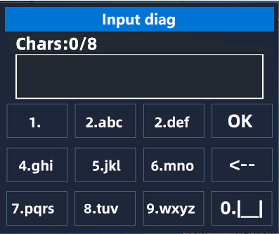 1-2 1-2 |
 1-3 1-3 |
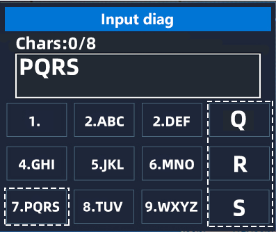 1-4 1-4 |
(In the text editing interface in the figure above, each box containing letters corresponds to the keys at the same position on the instrument keyboard) Case switching: press the “IN” key to switch the case of letters Text input: for example, input the capital letter “PQRS”, which corresponds to the “←” key (see Figure 1-4 above). First input the letter “P”, press the “←” key, input the letter “P” in the text box, and press the “IN” key to confirm the input of the letter “P”. Enter the letter “Q”, press the “←” key, the text box will enter the letter “P” again, and then press the “FN” key, the letter “P” will switch to the letter “Q” Enter the letter “R”, press the “←” key, the text box will enter the letter “P” again, and then press the “REST” key, the letter “P” will switch to the letter “R” Enter the letter “S”, press the “←” key, the text box will enter the letter “P” again, and then press the “EXIT” key, the letter “P” will switch to the letter “S” The input method of other letters is the same. Other input: when the input letter is not what you need, you can press the “< –” character corresponding to the “REST” key, and press the “REST” key once to delete one letter. To enter a value, just press and hold the corresponding key. For example, if you enter the value “1”, press and hold the “IN” key, and the number “1” will be entered in the text box. To input a symbol, first press the “IN” key to switch to figure 1-3 above, press the “T-ON” key to enter the down stroke symbol, and long press the “T-ON” key to enter the number “2” If you need to enter a space, press the “EXIT” key, and long press the “EXIT” key to enter the value “0” |
|
-29-
(Click to return to the directory)
Operation of variable interface(Enter the Modbus operation interface. After adding a variable, press the “I-TY” key to pop up the following variable operation interface) |
|---|

① : press the “IN” key to pop up the numeric keypad for modification ② : press “IN” to pop up the interface of adding variables ③ : ④ : Scanning device. Scan the device address according to the selected variable attribute (see the figure below for details) ⑤ : unified address. Set the device address of other variables to the same address as the selected variable address ⑥ : delete a selected variable ⑦ : delete all variables ⑧ : return to and exit the interface, or press the “EXIT” key directly to exit |
Scanning device(scan for unknown device address) |
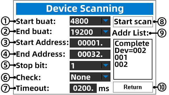 ① : select the starting baud rate, press the “IN” key to enter the selection mode, confirm the selection, and press the “IN” key ② : end baud rate selection, press the “IN” key to enter the selection mode, confirm the selection, and press the “IN” key ③ : start address setting, press the “IN” key to enter the editing mode, and press the “IN” key to confirm editing ④ : end the address setting, press the “IN” key to enter the editing mode, and press the “IN” key to confirm the editing ⑤ : stop bit selection ⑥ : check bit setting ⑦ : set the timeout duration. ⑧ : start scanning the device and press the “IN” key to start (Note: scanning requires the address and instruction parameters of variables, so you must add a variable or use the existing variable before scanning the device) ⑨ : address table. If the device responds, it will automatically fill the address into the address table. After scanning, the address table will display the number of devices responded. As shown in the figure above, “Dev = 002” indicates that the scanned addresses range from 1 to 32, and only “001” and “002” respond to the scanning. Then move the cursor to “Addr list:” press the “IN” key to enter the address table, select the responded device address, press the “IN” key, the scanning interface will exit automatically, and the responded device variable address will be modified automatically ⑩ : return to and exit the interface, or press the “EXIT” key directly to exit |
-30-
(Click to return to the directory)
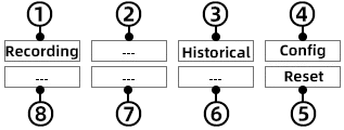
Paperless recorder function(Press the “FN” key to enter the function menu, and move the cursor to “Tools”. Press the “IN” key to enter the tools interface, move the cursor to the “Recorder”, and press the “IN” key to start the paperless recorder) |
|---|
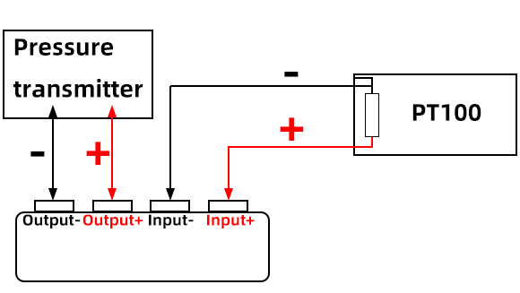
Recorder purpose: in the process of on-site debugging, if the occurrence time of the problem is uncertain, the recorder function can be used to record the signal change trend in the form of curve. After recording, the historical data can also be exported to personal computer for printing or screenshot analysis. Parameters: Capacity: 20000 recording points (1 point equals 1 second) Channel: two channels Recording interval: 0.1s-999.9s
① : value of signal channel “1” ② : value of signal channel “2” ③ : scale of signal channel “1” ④ : storage occupancy ⑤ : scale of signal channel “2”
① : start recording. Corresponding to “IN” key ②: ③ : history. Corresponding to “OUT” key ④ : configuration. Corresponding to “FN” key ⑤:Reset key, corresponding to the key “REST” Long press the “REST” key to reset the recording process, but the recording history will be automatically saved, and restarting the recording will automatically delete the previous recording history ⑥: ⑦: ⑧ :
Start recordingBefore using the recorder, the setting of the signal source is the most important part, so first determine what signal type to use as the signal source. For example: to record the temperature of PT100 temperature sensor. Pressure transmitter with pressure value range of 0-100kpa. The wiring diagram is shown in the figure below:
|

-31-
(Click to return to the directory)
Recorder settings(Press “FN” key for recorder setting.) (”Config” corresponds to the key “FN”) |
|
|---|---|
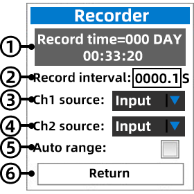 |
① : according to the user’s settings, the recorder will automatically calculate the length of time that can be recorded ② : the greater the interval, the longer the recording time will be ③ : ch1 signal source. For signal source setting, you can select “Output”/”Input”/”Modbus”/”Temp”/”CPU T” ④ : CH2 signal source. For signal source setting, you can select “OFF”/”Output”/”Input”/”MODBUS”/”Temp”/”CPU T” ⑤ : automatic range. The curve screen of mr9270 series displays 320 points. After using this function, the curve Y axis will be displayed in the range of maximum and minimum values within 320 points ⑥:return to and exit the interface, or press the “EXIT” key directly to exit |
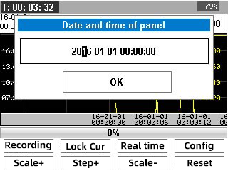
Start recording. Press the “IN” key to automatically pop up the time setting interface shown in the figure below. Press the “↑”, “↓”, “←” and “→” keys to set the time. After the time is set, press the “IN” key to confirm and automatically exit the time setting interface and start recording at the same time “Recording” corresponds to the “IN” key
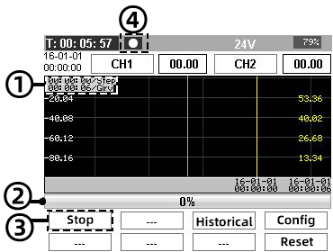
After recording, there will be some changes in the interface of keys. “Recording” becomes “Stop”, and the icon of recording data will appear in the status bar of the screen
① : the previous row is the time when the cursor moves one step at a time, and the next row is the time length of each grid ② : storage occupancy bar ③ : Pause key, corresponding to the “IN” key. When recording is started, “Recording” will change to “Stop”. Long press the “IN” key to pause recording, and the record will be saved automatically. If you need to record again, you can only long press the “REST” key to reset the record before you can start recording again. Restarting recording will automatically delete the last recorded data ④ : icon for recording data. If the recording icon appears in the status bar, it indicates that the recorder is still recording, and if it disappears, it indicates that it stops |
|
-32-
(Click to return to the directory)
View record history(press the “OUT” key to view the recorded history.) |
|---|
Press the “OUT” key to view the recorded history, and the key will change at the same time. For details, please refer to the figure below (Note: viewing the history in the process of recording will not affect the recording)
① : record / stop. Corresponding to the “IN” key, long press the “IN” key to pause the recording and save the recorded data at the same time ② : lock the cursor. Corresponding to the “T-ON” key, the function is to make the cursor not move, but only move the curve (use the direction key to move the cursor) ③ : real time curve / view history. Corresponding to “OUT” key ④:configuration. Corresponding to “FN” key ⑤ :press and hold the “REST” key to reset. Corresponding to “REST” key ⑥ : time scale -. Corresponding to the “O-TY” key, change the time length of the first grid ⑦ : step +. Corresponding to “”↑”” key, change the time length of each step of cursor movement, step – corresponding to “↓” key ⑧: time scale +. Corresponding to the “I-TY” key, change the time length of the first grid |


-33-
(Click to return to the directory)
Record data export
Click to download the upper computer software
|
Step 1:Plug in the USB cable to connect the computer (see Figure 1-1 below) ①:Data registered by recorder ②:The connection icon appears, indicating that the connection is successful
(1-1) |
|
|---|---|
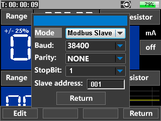
Step 2: press the ‘menu’ key to enter the function menu, and move the cursor to ‘communication settings’ (see the following figure) Then change the mode to ‘USB MODBUS’ |
|
(1-2) |
(1-3) |
(1-4) |
(1-5) |
|
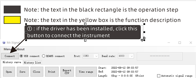
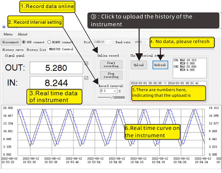
Step 3: open the downloaded upper computer software, extract the file, find the ‘Mr.Signal.exe’ file, and double-click it to run it (the following figure is the operation interface) |
|
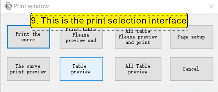
This is the text encoding of the yellow rectangle1.Record data online 2. Record interval setting 3.Real time data of instrument 4.No data, please refresh 5.There are numbers here, indicating that the upload is successful 6.Real time curve on the instrument 7. This is the browsing bar. You can drag it with the mouse. Drag the two ends of the browsing bar with the mouse to zoom the curve 8. Select a curve and click the right mouse button to enlarge the selected curve 9. This is the print selection interface |
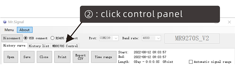
This is the text encoding of the black rectangle① : if the driver has been installed, click this button to connect the instrument ② : click control panel ③ : Click to upload the history of the instrument ④ : print out the data |
|
|
|


-34-